+1-866-7SMARTD (1-866-776-2783)

SDB-2-2150-A | 3~600V | 15kW/20HP-22A | S3
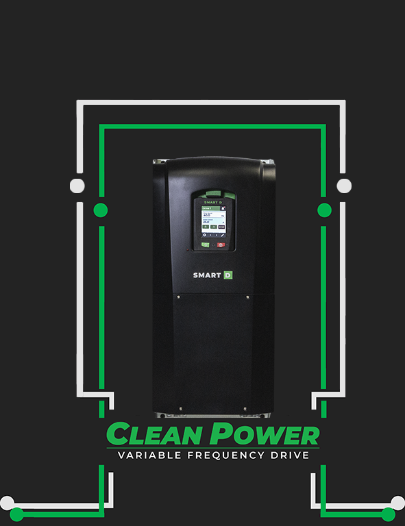
Clean Power Variable Frequency Drive, input 3x 600V, rated output 22A, IP20, embedded AFE
Main features
- Variable frequency drive for AC motors
- Pure sine wave 3-phase power output
- Clean Voltage sine wave, V/f open and close loop
- Field Oriented Control open and close loop
- Multifunctional, digital and analog IOs
- Built-in torque deactivation inputs
- 24 VDC power supply input
- Dual Ethernet port
- Fire emergency mode
- Configurable Linear Ramps
- Starting torque boost
- Integrated EMC filters
- Set, monitor, and control it with an app
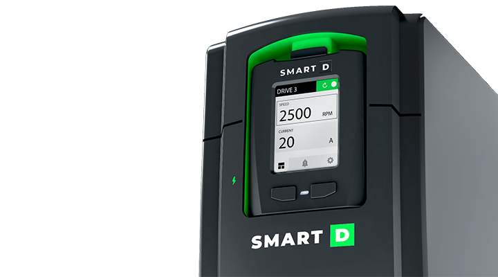
- Pluggable display
- Natural language user interface
Download the product datasheet:
![]()
Description
The SmartD Clean Power Variable Frequency Drive is a compact AC drive utilizing SmartD’s patented own algorithms combined with WBG transistor technology. Producing a clean and pure sine wave to power and control 3-phase AC induction motors has never been easier. The SmartD VFD has essential features built-in for space, wiring and time savings, it eliminates the need for filters on the output and input, and guarantees longer motor lifetime.
Cette publication est également disponible en : English
SDB-2-2150-A | 3~600V | 15kW/20HP-22A | S3 specs
Général
| Product function | Variable frequency drive for AC motors |
| Controlled motors | Asynchronous 3-phases motors |
| Control Methods | Clean Voltage sine wave, V/f open and close loop. indirect Field Oriented Control (iFOC) open and close loop |
Alimentation de puissance
| Input Power Voltage | VAC | 3~600 -15% / +10% | |
| Input Power Frequency | Hz | 50 and 60 +/- 5% | |
| Input line current | A rms | Rated at 50 °C (122 °F) | 23 |
| Apparent power | kVA | @ 600 V | 24 |
| Prospective Line Isc | kA | 50 kA | |
| THDi | % | from 80…100 % of load conforming to IEC 61000-3-12 | <5 |
Sortie de puissance
| Output Current | A rms | Normal operation (continuously available without overload) at 50 °C (122 °F) | 22A |
| Heavy duty operation at 50 °C (122 °F) | 17A | ||
| Motor Power kW normal duty (1) | 3x400VAC 50/60Hz | – | |
| Motor Power kW heavy duty (1) | – | ||
| Motor Power HP normal duty (1) | – | ||
| Motor Power HP heavy duty (1) | – | ||
| Motor Power kW normal duty (1) | 3x460VAC 50/60Hz | – | |
| Motor Power kW heavy duty (1) | – | ||
| Motor Power HP normal duty (1) | – | ||
| Motor Power HP heavy duty (1) | – | ||
| Motor Power kW normal duty (1) | 3x560VAC 50/60Hz | max 15KW | |
| Motor Power kW heavy duty (1) | max 11kW | ||
| Motor Power HP normal duty (1) | 20 HP | ||
| Motor Power HP heavy duty (1) | 15 HP | ||
| (1) Motor power values are indicative. They vary with the motor type, technology, and manufacturer. The variable frequency drive must not be selected from the motor power rating The variable frequency drive must be selected by skilled and experienced personnal. The variable frequency drive must be selected according to the motor FLA, the load’s driving force and the movement cycle, and the operating environment. | |||
| Maximum Transient Output Current | Normal operation | 25 A 110% of Normal Duty current during 60s every 10 min at 40 °C (104 °F) | |
| Heavy duty operation | 26 A 110% of Normal Duty current during 60s every 10 min at 40 °C (104 °F) | ||
| Permissible temporary current boost (motor starting) | Normal operation | ≥ 70 A at 50 °C (122 °F) during 2s | |
| Heavy duty operation | ≥ 70 A at 50 °C (122 °F) during 2s | ||
| Short-circuit current for immediate tripping | ≥ 105 A at 50 °C (122 °F | ||
| Output Frequency range of the drive | 0.001 to 0.5 kHz | ||
| Speed drive output Frequency | 0.1 to 120 Hz | ||
| Nominal switching frequency | 105 kHz | ||
| effective switching frequency | 210 kHz | ||
| efficiency | 8 points graph as per IEC61800-9 | ≥ 96% | |
| IE Class | 2 | ||
| -15…50 °C without derating | |||
| Deratings | Ambient temperature derating | >50…60 °C , Derate 2% for every 1 °C (1.8 °F) | |
| Altitude derating | no derating up to 2000 m | ||
Freinage
| Braking | Regenerative braking through AFE |
Entrée d'alimentation auxiliaire
| Voltage | 24 VDC |
| Limits | 20.4 VDC to 28.8 VDC |
| Built in protection of auxiliary power input | Reverse polarity and overvoltage |
E/S numériques
| Standard to comply with | IEC 61131-2 type 1 | ||
| Digital input numbers | 6 | ||
| Digital inputs common terminal | 1 | ||
| inputs 1 and 2 | Settable by user | usable for encoder | |
| inputs 3 to 6 | Settable by user | settable by user | |
| input logic | wire-able as sink or source, configurable by software default: source | ||
| Source mode logic thresholds | ON: 18 .. 24V / OFF: 0 .. 6V | ||
| Sink mode logic thresholds | ON: 0 .. 6 V / OFF: 18 .. 24 V | ||
| Current consumption | 6mA | ||
| Auxiliary Output power for digital inputs | +24VDC (20% .. +20%) / 100 mA | ||
| Built-in protection of Auxiliary output power | overcurrent and overvoltage | ||
| Torques Deactivation inputs | Number of inputs | 2 | |
| stop category | category 0 | ||
| input reaction time | < 20 ms | ||
| input filtering time | 3 ms | ||
| Nominal voltage enabling input | 24V | ||
| Maximum input voltage | 28.8V | ||
| Logic threshold | 10V (+/- 5V) | ||
| Low state maximum voltage for disable torque | 5V | ||
| Digital ouput numbers | 3 | ||
| relay 1 | relay output SPDT (form C) | NO Contact | Resistive load, AC: 5 A @ 250 V / DC 5 A @ 30 V |
| NC Contact | Resistive load, AC: 3 A @ 250 V / DC 3 A @ 30 V | ||
| relay 2 and 3 | relays output NO (form A) | Resistive load, AC: 3 A @ 250 V / DC 3 A @ 30 V |
E/S analogiques
| Analog input numbers | 3 | |
| Analog input types | settable by users | 0..10VDC 0..20mA / 4..20mA 0..24VDC Impedance to read PTC temperature sensor |
| Input impedance | 0..10VDC: input impedance > 3.5 k Ohms 0..20mA / 4..20mA: input impedance 165 Ohms 0..24VDC: input impedance > 3.5 k Ohms | |
| Resolution | 12 bits | |
| Sampling time | 2ms | |
| Accuracy | ± 1% at 25 °C (77 °F) / ± 2% for a temperature variation of 60 °C (108 °F) | |
| Reference power supply for potentiometer | +10 VDC / tolerance ± 2% for the temperature range of 20 °C to 30 °C / Current : maximum 10 mA, short circuit protected | |
| Analog ouput numbers | 2 | |
| Analog output types | settable by users | 0..10VDC ( ≥ 15 mA) 0..20mA / 4..20mA |
| Analog output impedeances | 0..10VDC: output impedance 500 Ohms minimum 0..20mA / 4..20mA: output impedance 500 Ohms maximum | |
| Resolution | 12 bits | |
| Sampling time | 2ms | |
| Accuracy | ± 1% at 25 °C (77 °F) / ± 2% for a temperature variation of 60 °C (108 °F) | |
| Analog outputs built-in protection | overvoltage and overcurrent |
Communication
| Embedded ports on 2 RJ45 | Modbus TCP | BACnet IP |
| Wireless for Settings | BLE |
Dimensions
| Width | 301 mm / 11.85″ |
| Height | 650 mm / 25.59″ |
| Depth | 251 mm / 9.88″ |
| Net weight | 30 kg / 66 lb |
Environnement
| Relative humidity | 5…95 % without condensation conforming to IEC 60068-2-3 |
| Ambient air temperature for operation | -15…50 °C without derating 50…60 °C with derating factor 2% for every 1 °C (1.8 °F) » |
| Ambient air temperature for storage | -40…70 °C |
| Cooling | Integrated, replaceable fans |
| Operating altitude | <=2000 m without derating |
| Environmental characteristic | Chemical pollution resistance class 3C3 conforming to EN/IEC 60721-3-3 Dust pollution resistance class 3S3 conforming to EN/IEC 60721-3-3 |
| Ingress Protection IP | IP20 |
| Protection Degree | UL (nema) type 1 |
Normes applicables
| Functionnal safety | UL/IEC 61800-5-1 :2007+AMD:2016CSV |
| EMC | IEC 61800-3 : 2017 emissions ; IEC 61000-4 immunity; IEC 61000-4-11 -34 voltage variations |
| Harmonics | IEC 61000-3-12 ; IEEE 519 |
| Generique | IEC 61800-2 : 2021 |
| EcoDesign / Energy efficiency | IEC 61800-9 |
| Safety standard ( STO) | IEC 61508 part 1 and part2 ; IEC 62061 :2021 |
| Cybersecurity | IEC 62443 |
| Environmental | IEC 60068-2 ; WEEE directive ; RoHS |
| CERTIFICATIONS | UL: pending |
Général
Alimentation de puissance
Sortie de puissance
Freinage
Entrée d'alimentation auxiliaire
E/S numériques
E/S analogiques
Communication
Dimensions
Environnement
Normes applicables
Général
| Product function | Variable frequency drive for AC motors |
| Controlled motors | Asynchronous 3-phases motors |
| Control Methods | Clean Voltage sine wave, V/f open and close loop. indirect Field Oriented Control (iFOC) open and close loop |
Alimentation de puissance
| Input Power Voltage | VAC | 3~600 -15% / +10% | |
| Input Power Frequency | Hz | 50 and 60 +/- 5% | |
| Input line current | A rms | Rated at 50 °C (122 °F) | 23 |
| Apparent power | kVA | @ 600 V | 24 |
| Prospective Line Isc | kA | 50 kA | |
| THDi | % | from 80…100 % of load conforming to IEC 61000-3-12 | <5 |
Sortie de puissance
| Output Current | A rms | Normal operation (continuously available without overload) at 50 °C (122 °F) | 22A |
| Heavy duty operation at 50 °C (122 °F) | 17A | ||
| Motor Power kW normal duty (1) | 3x400VAC 50/60Hz | – | |
| Motor Power kW heavy duty (1) | – | ||
| Motor Power HP normal duty (1) | – | ||
| Motor Power HP heavy duty (1) | – | ||
| Motor Power kW normal duty (1) | 3x460VAC 50/60Hz | – | |
| Motor Power kW heavy duty (1) | – | ||
| Motor Power HP normal duty (1) | – | ||
| Motor Power HP heavy duty (1) | – | ||
| Motor Power kW normal duty (1) | 3x560VAC 50/60Hz | max 15KW | |
| Motor Power kW heavy duty (1) | max 11kW | ||
| Motor Power HP normal duty (1) | 20 HP | ||
| Motor Power HP heavy duty (1) | 15 HP | ||
| (1) Motor power values are indicative. They vary with the motor type, technology, and manufacturer. The variable frequency drive must not be selected from the motor power rating The variable frequency drive must be selected by skilled and experienced personnal. The variable frequency drive must be selected according to the motor FLA, the load’s driving force and the movement cycle, and the operating environment. | |||
| Maximum Transient Output Current | Normal operation | 25 A 110% of Normal Duty current during 60s every 10 min at 40 °C (104 °F) | |
| Heavy duty operation | 26 A 110% of Normal Duty current during 60s every 10 min at 40 °C (104 °F) | ||
| Permissible temporary current boost (motor starting) | Normal operation | ≥ 70 A at 50 °C (122 °F) during 2s | |
| Heavy duty operation | ≥ 70 A at 50 °C (122 °F) during 2s | ||
| Short-circuit current for immediate tripping | ≥ 105 A at 50 °C (122 °F | ||
| Output Frequency range of the drive | 0.001 to 0.5 kHz | ||
| Speed drive output Frequency | 0.1 to 120 Hz | ||
| Nominal switching frequency | 105 kHz | ||
| effective switching frequency | 210 kHz | ||
| efficiency | 8 points graph as per IEC61800-9 | ≥ 96% | |
| IE Class | 2 | ||
| -15…50 °C without derating | |||
| Deratings | Ambient temperature derating | >50…60 °C , Derate 2% for every 1 °C (1.8 °F) | |
| Altitude derating | no derating up to 2000 m | ||
Freinage
| Braking | Regenerative braking through AFE |
Entrée d'alimentation auxiliaire
| Voltage | 24 VDC |
| Limits | 20.4 VDC to 28.8 VDC |
| Built in protection of auxiliary power input | Reverse polarity and overvoltage |
E/S numériques
| Standard to comply with | IEC 61131-2 type 1 | ||
| Digital input numbers | 6 | ||
| Digital inputs common terminal | 1 | ||
| inputs 1 and 2 | Settable by user | usable for encoder | |
| inputs 3 to 6 | Settable by user | settable by user | |
| input logic | wire-able as sink or source, configurable by software default: source | ||
| Source mode logic thresholds | ON: 18 .. 24V / OFF: 0 .. 6V | ||
| Sink mode logic thresholds | ON: 0 .. 6 V / OFF: 18 .. 24 V | ||
| Current consumption | 6mA | ||
| Auxiliary Output power for digital inputs | +24VDC (20% .. +20%) / 100 mA | ||
| Built-in protection of Auxiliary output power | overcurrent and overvoltage | ||
| Torques Deactivation inputs | Number of inputs | 2 | |
| stop category | category 0 | ||
| input reaction time | < 20 ms | ||
| input filtering time | 3 ms | ||
| Nominal voltage enabling input | 24V | ||
| Maximum input voltage | 28.8V | ||
| Logic threshold | 10V (+/- 5V) | ||
| Low state maximum voltage for disable torque | 5V | ||
| Digital ouput numbers | 3 | ||
| relay 1 | relay output SPDT (form C) | NO Contact | Resistive load, AC: 5 A @ 250 V / DC 5 A @ 30 V |
| NC Contact | Resistive load, AC: 3 A @ 250 V / DC 3 A @ 30 V | ||
| relay 2 and 3 | relays output NO (form A) | Resistive load, AC: 3 A @ 250 V / DC 3 A @ 30 V |
E/S analogiques
| Analog input numbers | 3 | |
| Analog input types | settable by users | 0..10VDC 0..20mA / 4..20mA 0..24VDC Impedance to read PTC temperature sensor |
| Input impedance | 0..10VDC: input impedance > 3.5 k Ohms 0..20mA / 4..20mA: input impedance 165 Ohms 0..24VDC: input impedance > 3.5 k Ohms | |
| Resolution | 12 bits | |
| Sampling time | 2ms | |
| Accuracy | ± 1% at 25 °C (77 °F) / ± 2% for a temperature variation of 60 °C (108 °F) | |
| Reference power supply for potentiometer | +10 VDC / tolerance ± 2% for the temperature range of 20 °C to 30 °C / Current : maximum 10 mA, short circuit protected | |
| Analog ouput numbers | 2 | |
| Analog output types | settable by users | 0..10VDC ( ≥ 15 mA) 0..20mA / 4..20mA |
| Analog output impedeances | 0..10VDC: output impedance 500 Ohms minimum 0..20mA / 4..20mA: output impedance 500 Ohms maximum | |
| Resolution | 12 bits | |
| Sampling time | 2ms | |
| Accuracy | ± 1% at 25 °C (77 °F) / ± 2% for a temperature variation of 60 °C (108 °F) | |
| Analog outputs built-in protection | overvoltage and overcurrent |
Communication
| Embedded ports on 2 RJ45 | Modbus TCP | BACnet IP |
| Wireless for Settings | BLE |
Dimensions
| Width | 301 mm / 11.85″ |
| Height | 650 mm / 25.59″ |
| Depth | 251 mm / 9.88″ |
| Net weight | 30 kg / 66 lb |
Environnement
| Relative humidity | 5…95 % without condensation conforming to IEC 60068-2-3 |
| Ambient air temperature for operation | -15…50 °C without derating 50…60 °C with derating factor 2% for every 1 °C (1.8 °F) » |
| Ambient air temperature for storage | -40…70 °C |
| Cooling | Integrated, replaceable fans |
| Operating altitude | <=2000 m without derating |
| Environmental characteristic | Chemical pollution resistance class 3C3 conforming to EN/IEC 60721-3-3 Dust pollution resistance class 3S3 conforming to EN/IEC 60721-3-3 |
| Ingress Protection IP | IP20 |
| Protection Degree | UL (nema) type 1 |
Normes applicables
| Functionnal safety | UL/IEC 61800-5-1 :2007+AMD:2016CSV |
| EMC | IEC 61800-3 : 2017 emissions ; IEC 61000-4 immunity; IEC 61000-4-11 -34 voltage variations |
| Harmonics | IEC 61000-3-12 ; IEEE 519 |
| Generique | IEC 61800-2 : 2021 |
| EcoDesign / Energy efficiency | IEC 61800-9 |
| Safety standard ( STO) | IEC 61508 part 1 and part2 ; IEC 62061 :2021 |
| Cybersecurity | IEC 62443 |
| Environmental | IEC 60068-2 ; WEEE directive ; RoHS |
| CERTIFICATIONS | UL: pending |
*Les spécifications sont susceptibles de changer sans préavis.
Bénéfices

Harmoniques ultra-faibles
Le Clean Power VFD ne crée que de très faibles harmoniques, réduisant le bruit électrique et augmentant l’efficacité énergétique de votre équipement.

Sans filtre
Le Clean Power VFD n’a pas besoin de filtres, ce qui permet un fonctionnement rentable et sans entretien de votre équipement.
Active Font End (AFE)
Le Clean Power VFD est doté d’un AFE qui permet d’obtenir un facteur de puissance proche de l’unité, des harmoniques très faibles et un freinage régénératif pour une meilleure efficacité énergétique.

Encombrement divisé par 2
Le Clean Power VFD étant de conception compacte et éliminant le besoin de filtres, il permet de gagner jusqu’à 50 % d’espace et de simplifier le câblage de l’équipement.

Signal propre
Le Clean Power VFD utilise la dernière technologie de composants électroniques de puissance, un algorithme breveté et des filtres intégrés, il produit une onde sinusoïdale propre.

Durée de vie prolongée du moteur
Les performances avancées du Clean Power VFD réduisent les contraintes sur l’isolation du moteur, les dommages aux roulements et le bruit électrique, ce qui prolonge la durée de vie du moteur.
// a la poursuite de l'énergie propre
Notre aventure du Clean Power VFD
Cliquez sur l’image pour lire l’histoire
INCEPTION:Simon Leblond et Simon Caron créent SmartD Technologies Inc, en 2018, à Montreal Quebec.

INNOVATION: SmartD développe la première technologie de variateur de fréquence (VFD) basée sur des semi-conducteurs à large bande interdite sur le marché - offrant une énergie propre d'une manière inédite. Pour atteindre ce niveau de technologie, SmartD travaille avec certains des spécialistes WBG les plus avancés de l'industrie.
IMPACT: PDes partenariats sont établis avec SE Ventures, le Groupe de recherche en électronique de puissance et commande industrielle (GRÉPCI), PME MTL, et la Chaire de recherche du Canada en conversion d’énergie électrique et en électronique de puissance.

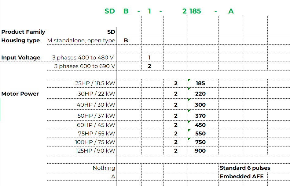
// SELECTION SIMPLE
Sélection de VFD Simplifiée
Plus simple de A à Z
La facilité commence par le choix du bon produit. La structure de l’offre du Clean Power VFD de SmartD est conçue pour faciliter la décision et éviter les choix complexes entre plusieurs niveaux d’options.
La facilité commence par le choix du bon produit. La structure de l’offre du Clean Power VFD de SmartD est conçue pour faciliter la décision et éviter les choix complexes entre plusieurs niveaux d’options.
Réservez une démonstration dès maintenant !
Clean Power VFD de SmartD est une réalité et il est prêt à révolutionner le contrôle des moteurs. Ne vous contentez pas de nous croire sur parole, voyez par vous-même.
// FAQ
Foire aux questions
Qu'est-ce qu'un variateur de fréquence?
Un variateur de Fréquence est un dispositif électronique qui contrôle la vitesse d'un moteur électrique en faisant varier la fréquence et la tension fournies au moteur.
Un variateur de vitesse ajuste la vitesse du moteur en fonction des besoins de la charge entraînée, ce qui permet de réduire considérablement la consommation d'énergie.
Un VFD, ou "Variable Frequency Drive" en anglais, est appelé couramment Variateur de vitesse, ou Variateur de fréquence, ou Convertisseur de fréquence dans les industries francophones .
Pourquoi le VFD Clean Power est-il le bon choix?
Le variateur de fréquence Clean Power de SmartD génère des signaux électriques sinusoïdaux purs dans un volume deux fois plus petit et deux fois plus efficace.
Oubliez les câbles encombrants et les filtres volumineux. Faites l'expérience de la puissance propre dans un encombrement compact.
Combien de temps faut-il pour installer le variateur de fréquence SmartD Clean Power?
3 câbles en entrée, 3 câbles en sortie. C'est tout Installez-le et laissez-le faire son travail en moins de 30 minutes.
Le SmartD Clean Power VFD fonctionnera-t-il avec nos systèmes existants?
Nos produits sont prêts pour l'IoT, la GTB et le SCADA.
Connectivité Ethernet et Modbus pour l'intégration aux systèmes Cloud, BMS et SCADA.
Le SmartD Clean Power VFD est-il disponible à l'achat?
Le SmartD Clean Power VFD sera disponible à l'achat au troisième trimestre 2022.