Learning Center
- Home
- Learning Center
Our Learning Center
This page’s objective is to share knowledge and vocabulary related to motors and drive.
Table of Contents
Bypass
Conductors’ sizes – Metric vs AWG
Deceleration
Derating
Digital Input Logic Connection
Efficiency
Efficiency VS Loss
Electromagnetic Compatibility (EMC)
FLA or FLC
Four Quadrants
Fuses
Grounding and Bonding
Input current vs Output current
Jump Frequency
Locked-Rotor Current
Motors
Normal Duty- Heavy Duty
Safety
Safe Torque Off
SIL
Sink and Source
Select a variable frequency drive
Speed
Speed range ratio (or speed ratio or speed range)
Slip
Torque and motion
Why Variable Frequency Drive?
A Variable Frequency Drive (VFD) is an essential device for adjusting the operations of both industrial and non-industrial processes based on various variables.
Industrial processes such as Pulp and Paper, Mining, Food & Beverage, and Textile, as well as non-industrial processes like HVAC, water treatment, draining, and irrigation, all require VFDs for efficient operations.
In particular, HVAC systems play a crucial role in creating and maintaining a comfortable environment in our offices, public buildings, shopping malls, and homes by adjusting airflow based on temperature and humidity. VFDs are instrumental in achieving this airflow adjustment.
The primary purpose of using VFDs is to match the speed or torque/power of the drive to the process requirements, depending on the specific application. By achieving these objectives, VFD users can reap numerous benefits, such as energy savings, improved system efficiency, reduced mechanical stress on machines, increased equipment lifetime, and reduced maintenance frequency. Additionally, VFDs can help lower noise levels on fans and pumps, among other things.
Alphabetical list of knowledge
Bypass
In situations where downtime is not an option, such as in a hospital surgery room or a data center, or where service interruptions can lead to spoilage, such as in a food warehouse, it is crucial to ensure uninterrupted operation of the motor(s) even if the Variable Frequency Drive (VFD) fails.
A common solution to this problem is to install a 2-contactor bypass. This mechanism enables the motor to bypass the VFD and continue running at full speed, ensuring uninterrupted delivery of the service despite the VFD failure.
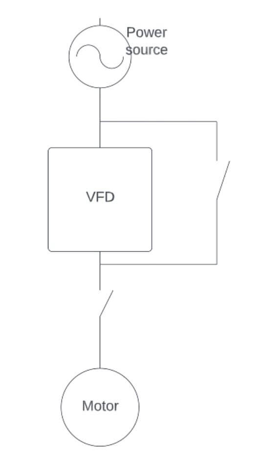
To safely replace a drive in this simple system, the power supply must be shut down. However, a more efficient solution is to incorporate a 3-contactor bypass.
A 3-contactor bypass includes an additional contactor before the VFD that disconnects the power supply to the VFD when it is in bypass mode. This allows for the motor to continue operating in the event of a VFD failure, while also enabling the VFD to be safely removed and replaced with a new unit without interrupting motor operation.
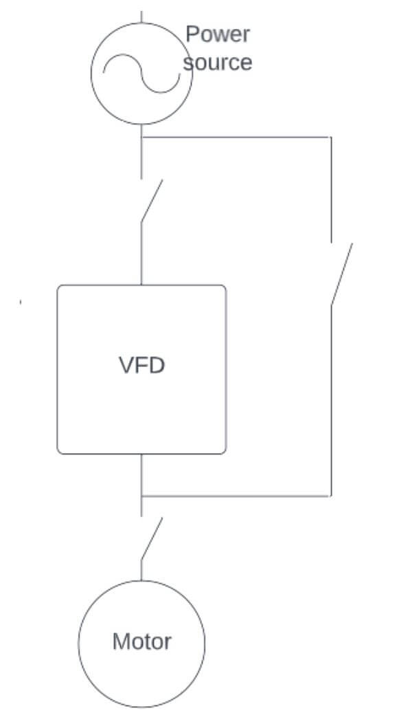
The key distinction between a 2-contactor bypass and a 3-contactor bypass is as follows:
- With a 2-contactor bypass, it is necessary to power off the system before replacing the VFD.
- In contrast, a 3-contactor bypass enables the VFD to be replaced while the motor continues to run in bypass mode.
The bypass is frequently controlled by a wired logic circuit that relies on either the alarm output relay of the VFD or a manual forced bypass operation.
Conductors’ sizes - Metric vs AWG
European cables are usually manufactured with metric conductors (identified by a mm2 cross section) while US-manufactured cables use the AWG size standards.
AWG | Diameter | Diameter | Cross | Copper | Common metric |
6 | 0.1620 | 4.115 | 13.3 | 1.296 |
|
7 | 0.1443 | 3.665 | 10.5 | 1.634 |
|
8 | 0.1285 | 3.264 | 8.37 | 2.061 |
|
9 | 0.1144 | 2.906 | 6.63 | 2.599 | 6.0 |
10 | 0.1019 | 2.588 | 5.26 | 3.277 |
|
11 | 0.0907 | 2.305 | 4.17 | 4.132 | 4.0 |
12 | 0.0808 | 2.053 | 3.31 | 5.211 |
|
13 | 0.0720 | 1.828 | 2.62 | 6.571 | 2.5 |
14 | 0.0641 | 1.628 | 2.08 | 8.286 |
|
15 | 0.0571 | 1.450 | 1.65 | 10.45 | 1.5 |
16 | 0.0508 | 1.291 | 1.31 | 13.17 |
|
17 | 0.0453 | 1.150 | 1.04 | 16.61 | 1 |
18 | 0.0403 | 1.024 | 0.823 | 20.95 | 0.75 |
19 | 0.0359 | 0.912 | 0.653 | 26.42 |
|
20 | 0.0320 | 0.812 | 0.518 | 33.31 | 0.5 |
Deceleration
During the deceleration phase, the motor speed exceeds the VFD output frequency, also known as the synchronous speed. As a result, the motor operates as a generator, and the energy is returned to the VFD, causing the DC voltage to increase. This phenomenon is known as “regeneration.” To prevent an overvoltage alarm, it is essential to set an appropriate deceleration time and to consume the regenerated energy in a braking resistor.
However, Clean Power VFDs are equipped with an active front end (AFE) that feeds the power grid with the regenerated energy, eliminating the need for a braking resistor.
The deceleration time can be calculated based on the mechanical attributes of the system, such as the motor and load inertia and the acceleration torque. Specifically:
Deceleration time = (target speed – starting speed) x J / Ca
Here, the target and starting speeds are measured in revolutions per second, J represents the total inertia of the motor and load (in kg.m2), and Ca is the acceleration torque, which is equal to 9.55 times the difference between the rated motor torque and the minimum load torque.
Derating
Electric motors are typically designed to operate at altitudes of 1000 meters or less above sea level.
At higher altitudes, the atmospheric pressure decreases, which can compromise the motor’s heat dissipation and, consequently, its temperature, insulation, and grease life during operation.
To ensure proper motor performance, specialized measures, such as derating, are required.
The same issue applies to variable frequency drives (VFDs) that control the motor.
At higher altitudes, the VFD’s heat dissipation also worsens due to the low atmospheric pressure. In the absence of manufacturer recommendations, it is common practice to derate both the motor and VFD by 3% every 300 meters (1000 feet) when the altitude exceeds 1000 meters.
The Clean Power VFDs design allow to operate without derating up to the altitude of 2000 m.
Digital Input Logic Connection
Sink and source logic connections refer to the current flow in DC circuits and are commonly associated with PLC I/O signals. In a sinking input or output circuit, the electric load is provided a path to the ground. In contrast, a sourcing input or output provides the voltage source for the electric load.
The digital inputs of the Clean Power VFD are compatible with both sink and source logic connections, and the selection can be made through software. The following images illustrates the two logics: sourcing (connection to PNP sensor) involves switching the +24V to the inputs, while sinking (connection to NPN sensor) involves switching the 0V to the inputs.
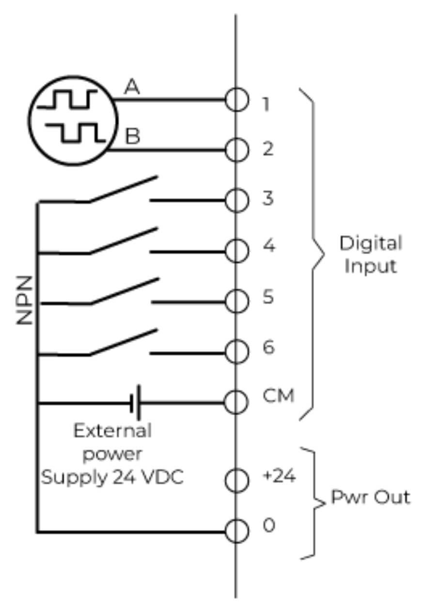
Figure 1: Sink logic connection with external power supply
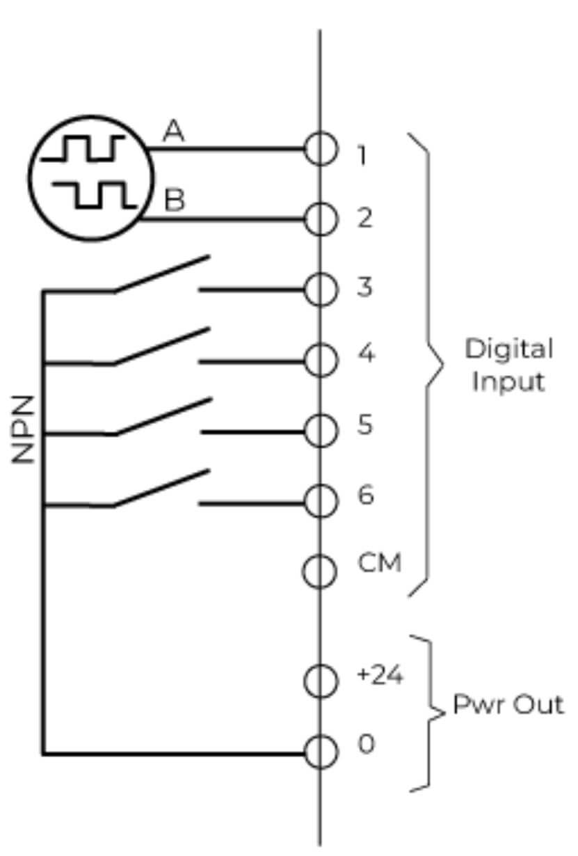
Figure 2: Sink logic connection using the internal power supply
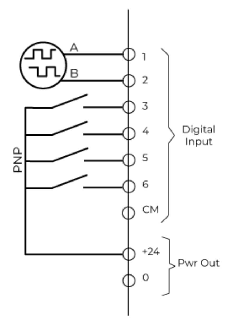
Figure 3: Source logic connection
Efficiency
To obtain an accurate understanding of efficiency, it’s crucial to consider the entire system instead of focusing on individual components. Efficiency can be defined as the ratio of output power to input power in any system. In our scenario, the mechanical power produced by the motor constitutes the output power, while the electrical power supplied to the VFD is the input power.

Electrical input power Pin, depends on voltage (U), current (I), and the power factor (cosϕ). The power factor tells us what proportion of the total electric power is active power and how much is so-called reactive power. To produce the required mechanical power, active power is required. Reactive power is needed to produce magnetization in the motor.

Mechanical output power Pout, depends on the required torque (T) and rotating speed (n).

During the transfer, from electrical energy to mechanical energy, the main losses are thermal. Both in the drive and in the motor.
Efficiency VS Loss
These two terms are often used interchangeably and can cause confusion. The output power of a VFD is the input power minus any losses. This is expressed as Ploss=Pinput-Poutput
When analyzing a complete system, from the grid connection to the motor, one can simply add up the losses of each individual component (such as contactors, fuses, VFD, filters, cables, and motor) to determine the total loss of the system.
Efficiency, on the other hand, is more of a performance metric and is calculated as Efficiency = Poutput/Pinput.
Electromagnetic Compatibility (EMC)
EMC compliance standards for Power Drive System (PDS) cover not just the VFD, but also the motor and all interconnecting elements such as control cables, motor cables, supply cables, contactors, junction boxes, etc., except for the driven load. The standards specify 2 different environment types (1st & 2nd Environment) based on the location of the point of common coupling (PCC). There are 4 different product categories (C1, C2, C3, and C4) that define varying limits for conducted RFI noise into the mains terminal, in the frequency range of 150KHz to 30MHz, depending on the rated voltage and current of the VFD, and whether or not it is installed by an EMC professional
- 1st Environment includes domestic premises and buildings/facilities which are directly connected to a low voltage (e.g. 230/400V) mains supply which also supplies buildings used for domestic purposes. Directly connected means that there is no intermediate transformer between these buildings.
- 2nd Environment includes all buildings/facilities which are not directly connected to a low voltage mains supply which also supplies buildings for domestic purposes. For example, a facility with a dedicated low voltage mains, supply transformer would be a 2nd Environment installation.
- Category C1 – this category applies to VFDs connected to a mains supply <1000 volts for use in the 1st Environment.
- Category C2 – this category applies to VFDs connected to a mains supply <1000 volts that when used in the 1st Environment will be installed and commissioned only by a professional. It defines a professional as a person or organization having the necessary skills in installing VFDs including their EMC aspects.
- Category C3 – this category applies to VFDs connected to a mains supply <1000 volts for use in the 2nd Environment.
- Category C4 – this category applies to VFDs connected to a mains supply ≥1000 volts or rated ≥400 amps or for the use in complex systems in the 2nd Environment.
FLA or FLC
While both terms are related to the current drawn by a motor, they have slightly different meanings and uses:
Motor FLA (Full Load Amperes):
This is the actual current drawn by the motor when it is operating at its rated horsepower and rated voltage.
You can find this value on the motor’s nameplate.
It is used for various purposes, including:
Selecting circuit breakers and overload protection devices for the motor circuit.
Calculating the power consumption of the motor.
Comparing the performance of different motors.
Motor FLC (Full Load Current):
This is a standard reference value for the current drawn by a motor of a particular size and type.
You can find these values in tables provided by electrical standards like the National Electrical Code (NEC) in the US.
It is typically used for initial circuit design and planning when the specific motor hasn’t been selected yet.
It is not always identical to the actual FLA of a specific motor, as there can be slight variations between different manufacturers and models.
Key Differences:
Source: FLA is based on the specific motor, while FLC is a general reference value.
Accuracy: FLA is more accurate for the specific motor, while FLC is an estimate.
Use: FLA is used for detailed calculations and selection, while FLC is used for initial planning.
In summary:
Use FLA when you have a specific motor and need accurate information about its current draw.
Use FLC for initial planning and design when the specific motor hasn’t been selected yet.
Four Quadrants
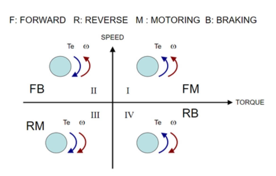
To meet certain application requirements, it may be necessary to operate the motor in both clockwise and counterclockwise directions. Additionally, depending on the application and load, the torque direction may also need to be reversed. This results in four possible combinations, known as the four quadrants.
Quadrant 1
The motor is running clockwise and the torque is in the same direction as the speed. This is acceleration.
Quadrant 2
The motor is running clockwise and the torque is in the opposite direction. This is deceleration.
Quadrant 3
The motor is running counterclockwise and the torque is in the same direction as the speed. This is acceleration.
Quadrant 4
The motor is running counterclockwise and the torque is in the opposite direction. This is deceleration.
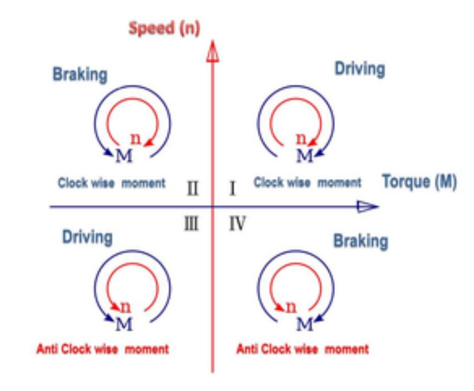
There are several diagrams of torque and speed on the web to illustrate the 4 quadrants.
Fuses
To ensure safety and protection, fuses are utilized to safeguard the input cable in the event of short-circuits and prevent damage to the VFD in case of a short-circuit within the drive. However, the recommendations for fuse types may vary depending on local regulations. For instance, in the IEC environment, high-speed aR fuse types are typically recommended, although gG fuses can also be utilized if they operate rapidly enough (max. 0.1 seconds). The operating time is influenced by the supply network impedance, as well as the cross-sectional area and length of the supply cable.
In the UL environment, NEC Article 430.52(C)(5) recommends the use of high-speed fuses for motor branch circuit protection in motor control systems that use solid-state devices such as VFDs and soft-starters. For instance, class J or class T fuse can be selected by the user. Class J fuses are fast-acting and time delay versions rated for 600 volts AC and can interrupt a minimum of 200,000 amps. The ampere ratings for the J-type fuses range from 1 to 600 amps. Class T fuses are also fast-acting and current limiting, rated for 300 volts AC and 600 volts AC versions, with ampere ratings ranging from 1 to 800 amps.
To define the fuse rating, the VFD nominal current rating (e.g. 34A for the 18.5kW clean power VFD) must be considered. The calculated value can be determined by multiplying the VFD rated current by 1.25 (for normal operation, continuously available without overload). For instance, a 34A current rating VFD, 1.25 x 34A = 42.25A. The manufacturer catalog of fuses should be consulted to select a fuse with a standard size just above the calculated value, which in this case would be a 50A fuse. The fuse voltage must also be greater than line voltage, and a 600 VAC fuse should be selected.
It is essential to always use UL compliant cables (copper and minimum temperature 75C / 167F) and fuse holders specified for the selected fuses to ensure safety and protection.
Grounding and Bonding
Grounded or grounding refers to the act of connecting an electrical circuit or conductive object to the ground, or to a conductive material that is connected to the ground.
On the other hand, bonded or bonding refers to the act of connecting two or more conductive objects to establish electrical continuity and conductivity. It is important to note that bonding does not necessarily mean grounding, as the connected objects may not be connected to the ground. However, bonding ensures that the metallic parts of the objects can form an electrically conductive path for electrical continuity.
Input current vs Output current
When measuring the input and output current of a VFD, you may observe that the output current is higher than the input current. This contradicts the belief that the output current should be lower than the input current due to a VFD’s efficiency being less than 100%.
The input current from the electric grid to the VFD is the real current that produces useful work or torque. The VFD’s output current to the motor has two components: the real current that generates useful work or torque (watts) and the reactive current that generates the magnetic field in the motor (vars).
The total output current from the VFD is the square root of the sum of squares of both the real current and reactive current. The real current is supplied by the electric grid while the reactive current is supplied by the DC bus capacitor inside the VFD. Therefore, it is possible for the output current of the VFD to be higher than the input current.

Jump Frequency
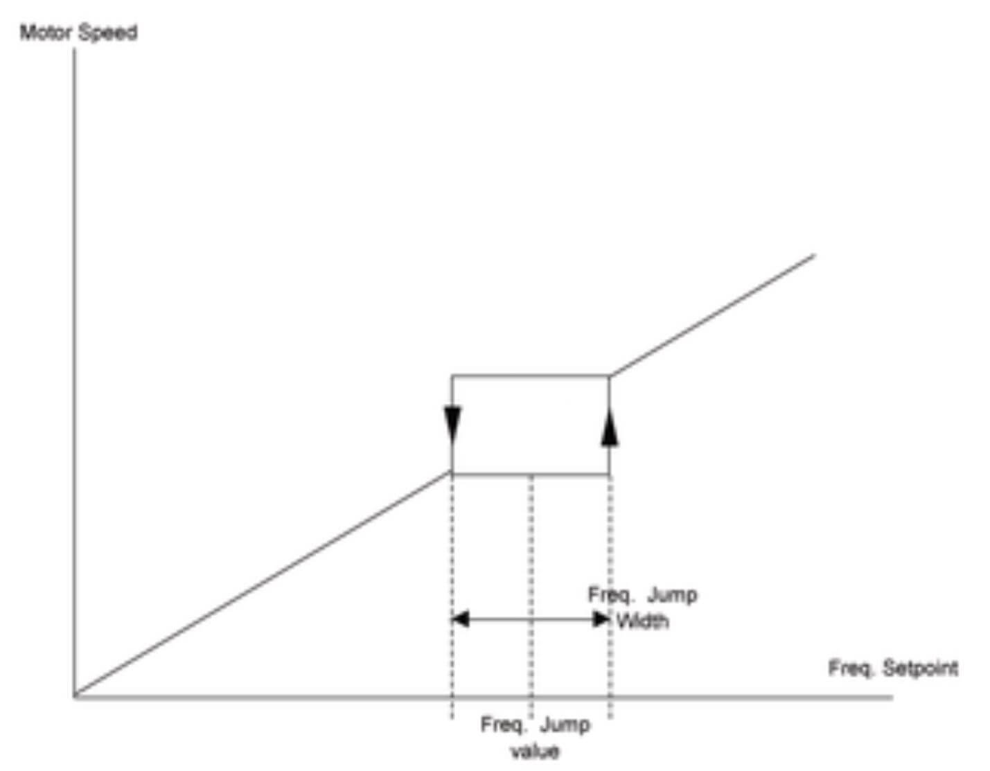
In order to prevent resonance in machinery or equipment, it is important to avoid the natural frequency of the mechanical system. The jump frequency feature allows for the specification of a dead band at a particular frequency. This feature includes the ability to set several jump frequencies independently, typically with parameters such as the jump frequency value and jump frequency width. When the frequency setpoint is entered at or near the jump frequency width, it is automatically adjusted by the drive. The motor is then smoothly accelerated or decelerated until the frequency setpoint is outside the range of the jump frequency band.
Locked-Rotor Current
Locked-rotor current is the steady-state current of a motor with the rotor locked and with rated voltage applied at rated frequency (nameplate values).
NEMA has designated a set of code letters to define locked-rotor kilovolt amperes-per-horsepower: KVA/Hp
KVA=(Rated volts x Inrush current x 1.732 (square root of 3))/1000
HP= as per motor nameplate
This code letter appears on the nameplate of all AC squirrel-cage induction motors.
NEMA | KVA/HP |
A | 0-3.14 |
B | 3.15-3.55 |
C | 3.55-3.99 |
D | 4.0-4.49 |
E | 4.5-4.99 |
F | 5.0-5.59 |
G | 5.6-6.29 |
H | 6.3-7.09 |
J | 7.1-7.99 |
K | 8.0-8.99 |
L | 9.0-9.99 |
M | 10.0-11.19 |
N | 11.2-12.49 |
P | 12.5-13.99 |
R | 14.0-15.99 |
S | 16.0-17.99 |
T | 18.0-19.99 |
U | 20.0-22.39 |
V | 22.4-and up |
For example: Determine the maximum locked-rotor current for a Code G, 460-volt, 3-phase, 25-HP motor.
Locked rotor current = ( 6.29 x 25 x 1000/√3 ) / 460 = 197 A
Motors
Whether in industrial fields or non-industrial fields, most of the moving processes and machines are driven by electric motors.
Cutting, crushing, forming, rolling, mixing, extruding, hoisting, conveying, pumping, blowing, compressing …there’s always an electric motor behind these actions.
Some say that the electric motor is the workhorse of processes.
Electric motors can be divided into AC and DC motors. AC motors, particularly squirrel cage motors, are the most used motors. We focus here on AC motors.
A VSD delivers 3 essential controls to the motor: its speed, torque, its power.
Without forgetting many other benefits, such as protection, and energy savings.
We must always consider the system made of the motor and the drive together!
Induction motors
Motors in which the magnetic field is induced (hence the name). They run slower than the magnetic field (slip), hence their designation as asynchronous. They generally run at a constant speed which changes slightly when mechanical loads are applied to the motor shaft. Due to its simplicity, robustness, and low cost, this type of motor is the most widely used and, in practical terms, is quite suitable for almost all types of machines.
It is possible to control the speed of induction motors by frequency inverters.
Synchronous motors:
Synchronous motors are three-phase AC motors that run at a fixed speed, without slip, and are generally applied for large outputs.
Motor lifetime:
The useful lifetime of the motor depends almost exclusively on the life of the winding insulation. The lifetime of a motor is affected by many factors, such as moisture, vibration, corrosive environments, and others. Among all of these factors, the most important is the working temperature of the employed insulation materials. An increase from 8 to 10 degrees above the rated temperature class of the insulation system can reduce the motor lifetime by half.
Normal Duty - Heavy Duty
Constant torque applications, such as extruders, conveyors, lifting equipment, compressors, or crushers, usually specify a Heavy-Duty VFD. These applications require a high overload tolerance with constant load torque.
In variable torque applications, which include centrifugal fans and pumps, a Normal Duty drive will suffice.
For these applications in which the torque requirements drop along with the speed, a high overload tolerance is not required.
Drives with a Heavy-Duty rating have a current overload of 150% of the rated current for one minute and can run at 100% current continuously. Normal Duty drives are robust enough for fans and pumps since they have a current overload rating of 110% for one minute, and can also run at 100% current continuously.
Most of the drives are rated both for Normal Duty and Heavy-Duty. Of course for different current capabilities.
e.g a variable frequency drive able to run a 20HP Normal Duty motor shall be also able to run a 15HP Heavy-Duty motor.
During setting, the user has to select normal to Heavy-Duty. Then the VFD will trip on overload and duration accordingly.
Safety
Within IEC 61508 there are basically two types of safety functions: high demand, and low demand.
A high-demand safety function is for a demand which occurs more often than once per year (e.g. once per day) and a low demand is for something which has an expected demand rate of less than once per year (e.g. once every 10 years).
There is no definition of “demand” in IEC 61508, but IEC TR 631161 defines a demand as an “event that causes the safety control system to perform the safety control function.” Within the process industry, a demand may also be referred to as a process update, or a process deviation.
IEC 61508 defines a third mode of operation called continuous mode, but the requirements are similar to the high-demand mode.
In low and high-demand modes two things need to happen for someone to get hurt.
1) The safety system needs to fail, and
2) a demand must occur while the safety system is in the failed state.
In continuous mode, an incident happens as soon as the safety system fails dangerously, as it is the safety system that is maintaining safety.
While IEC 61508 as a basic standard needs to cover both low and high-demand modes, this is not the case for sector-specific standards. For instance, machinery only has high demand and process control has mostly low demand.
Safe Torque Off
STO (Safe Torque Off) is a functional safety feature, built-in into the drive, to disable the output so that the drive cannot generate torque in the motor.
If STO1 or STO2 input does not have a +24V enable input signal, the drive is disabled to a high degree of integrity, where no single component failure, and only very unlikely combinations of multiple component failures could result in it being enabled.
SIL
SIL stands for “Safety Integrity Level”
SIL Classifications: There are four discrete integrity levels associated with SIL. SIL1, SIL2, SIL3 & SIL4; which is basically differentiated by the range of Risk Reduction Factor (RRF) and Mean Time to Failure (MTTF). Hence, the higher the RRF and MTTF, the higher the rating of SIL will be for the respective demand mode of failure. This is known as the Probability of Failure on Demand (PFD), which is a value that indicates the probability of a functional system failing to respond to a demand (for a particular consequence).
Sink and Source
Sourcing and Sinking are two terms that describe how current flows between the input and output devices of a control system and their power supply. This concept follows the basic electrical theory, which says that; for an electrical circuit to be complete, the conventional current should go from the DC+ terminal through a load to the DC- terminal. Therefore, Sourcing and Sinking only apply to DC input and DC output circuits.
Some people may find the concept of Sourcing and Sinking confusing, but it is actually quite simple. Sourcing and Sinking logic circuits are mainly related to digital VFD Input and Output (I/O) signals. A logic circuit is an electrical I/O circuit where the output depends on the input. The type of components and the direction of current flow define such circuits. A simple logic circuit can have a single binary (ON/OFF) output and one or more binary inputs. It can include any binary electrical or electronic devices, such as push buttons, switches, transistors, solid-state diodes, and relays.
In other words, the concept of Sourcing and Sinking in digital VFD I/O is all about determining the direction of conventional current flow in a logic circuit between two devices.
Look at the following illustration:
From the figure above, electric current is going from Device A to Device B. So, Device A is the sourcing device because it sends current to Device B, which then receives that current. Device B is the sinking device.
When current is going from Device B to Device A, as shown below, then Device B is the sourcing device and Device A is the sinking device. The reason is Device B sends current to Device A, which then receives the current.
Note: In every DC circuit where current flows between two devices, one of the devices will be the Sourcing device and the other will be the Sinking device.
In VFDs, a digital input will sense one of the possible binary states of a discrete field input device such as Closed or Open; Energized or De-Energized; ON or OFF; High or Low. Depending on the kind of digital input used in the VFD system and how it is connected to the field input device, DC current will either flow into or out of the input. This is where Sourcing and Sinking terms come into play.
In Source logic connection, the VFD accepts discrete field input devices that are sourcing the current … and the VFD is sinking the current,
while in Sink logic connection the VFD system provides a source of current and a connection to ground for the external discrete field input device.
Let’s use an analogy. Imagine you have a water pump that can be turned on or off by a valve. In this scenario, the water pump represents the output device, and the valve acts as the input device. Let’s explore how the concepts of sourcing and sinking apply to this system:
Sourcing (Source Logic):
- If the valve is the sourcing device, it provides the current (water flow) to the water pump.
- The water pump acts as the sinking device, receiving the water flow from the valve.
- In this case, the valve is like a faucet that supplies water to the pump when turned on.
Sinking (Sink Logic):
- Conversely, if the water pump is the sourcing device, it provides water to the valve.
- The valve becomes the sinking device, allowing water to flow from the pump.
- Think of this as the pump creating a pressure effect, pushing water to the valve when activated.
The reason why sinking and sourcing exist is that different devices have different wiring requirements. Some devices need to be supplied with voltage, while others need to be grounded. By using sinking or sourcing digital inputs, you can match the VFD with the external device and ensure a proper current flow.
Select a variable frequency drive
Choosing the right Clean Power Variable Frequency Drive (VFD) and motor for your application is essential for ensuring optimal performance, longevity, and system reliability.
Understanding the Application
Before selecting a Clean Power VFD and motor, it is crucial to understand the operating environment and the specific tasks to be performed. The selection process involves:
1. Motor Selection:
– Choose a motor based on the load’s driving force and movement cycles.
– Basic movement cycle: start > acceleration > constant speed > deceleration > stop.
2. VFD Selection:
– Select a Clean Power VFD capable of driving the chosen motor effectively.
Key Considerations in VFD Selection
1. Motor Current Rating
The primary consideration when selecting a VFD is the motor’s current rating.
The VFD must provide a current equal to or greater than the motor’s full load amperage (FLA). This ensures the motor can operate at its maximum capacity without the risk of underpowering.
Steps to Consider:
– Check the motor’s nameplate for its FLA.
– Ensure the VFD’s continuous current rating matches or exceeds this value.
2. Motor Operation Cycles
Understanding the motor’s operation cycles is crucial for choosing a VFD. This involves knowing how often the motor will start and stop, and the duration of these cycles.
Key Considerations:
– Frequent start/stop cycles can cause thermal stress.
– The VFD should be capable of handling the motor’s duty cycle.
3. Motor Potential Temporary Overload
Motors often encounter temporary overload conditions that the VFD must handle without tripping.
Temporary Overload Capacity:
– VFDs are typically rated for overload conditions, such as 110% of the VFD’s rated current for 60 seconds.
– Ensure the VFD’s overload rating aligns with the motor’s overload requirements.
4. Ambient Temperature
The ambient temperature where the VFD operates significantly affects its performance and lifespan. Higher temperatures can reduce the VFD’s capacity and efficiency.
Temperature Adjustments:
– Check the VFD’s de-rating, which shows how current capacity decreases with rising ambient temperatures.
– Select a VFD with sufficient capacity to handle expected temperature ranges.
5. Duty Cycle (IEC Definition)
The duty cycle, as defined by IEC standards, represents the operating time and rest time of the motor.
Duty Cycle Categories:
– Continuous operation (S1): Running at constant load for a long period.
– Short-time duty (S2): Running at a constant load for a limited time.
– Intermittent periodic duty (S3-S9): Cycles of running and stopping.
VFD Selection:
– Match the VFD to the specific duty cycle category of your motor application.
– Ensure the VFD can handle the motor’s operating pattern.
6. Service Factor (NEMA Definition
The service factor defined by NEMA indicates the motor’s ability to operate over its rated load under specific conditions.
Service Factor Implications:
– A motor with a service factor of 1.15 can operate at 115% of its rated load without damage.
– Select a VFD that can handle the motor’s rated load and service factor. This might mean choosing a VFD with a higher current capacity.
Additional Considerations for Specific Operations
1. Start
– The motor torque must be larger than the load starting torque.
2. Acceleration
– The motor torque must be larger than the load torque required for acceleration:
– Motor torque > Load torque + Acceleration torque.
– Acceleration torque = (total inertia of the system * (target speed – starting speed)) / (9.55 * acceleration time).
3. Deceleration
– During deceleration, the motor acts as a generator, and energy flows back into the Clean Power VFD.
– The deceleration capability is determined by the Clean Power VFD’s ability to consume or regenerate this energy.
– Ensure the deceleration time is correctly set to avoid triggering alarms or entering a “self-protective” lock state.
4. Constant Speed
– Check that the motor temperature rise specification is compatible with both the movement cycles and the operating environment.
– During acceleration or constant speed operation, the Clean Power VFD’s capacity is limited by the peak current it can deliver to the motor.
– Ensure that the rated current output and overload capacity are the correct size for the application.
5. Clean Power VFD Current Ratings
Clean Power VFD current ratings are provided for Normal-duty operation = continuous operation (S1) / Running at constant load for a long period. It’s an RMS value.
– It’s the current rating suitable for variable torque applications where torque drops with speed. Overload capacity: 110% of the VFD nominal output current for 60 seconds every 10 minutes at 40°C.
6. Driving Multiple Motors
While it is possible to drive multiple motors with a single Clean Power VFD, additional precautions are necessary:
6.1. VFD Current Rating:
– Select a Clean Power VFD with a rated output current greater than the combined total of the individual motor currents.
– V/F control must be selected to drive multiple motors with one VFD.
6.2. Considerations for Multiple Motors:
– For a single motor: VFD rated output current > motor’s rated current.
– For multiple motors: VFD rated output current > total rated motor current.
– If several motors are sequentially started: VFD rated output current > total rated current of started motors plus the starting current of the next motor.
6.3. Thermal Protection**:
– Add a thermal relay for each motor on the Clean Power VFD output side.
– Auxiliary thermal relay contacts should stop or disable the drive.
6.4. Continuous Drive at Low Speed:
– Install a temperature detection device on the motors since they cannot be protected by the VFD’s thermal function.
7. Acceleration and Deceleration Time
When acceleration or deceleration time is restricted, the selection of the VFD cannot be fully based only on matching the VFD current capacity with the motor’s rated current.
Aggressive acceleration/deceleration rates will lead to higher currents, potentially causing overload or overcurrent faults. The system’s capacity (VFD + motor) must be selected to satisfy the predetermined acceleration/deceleration time.
Ensure that the Clean Power VFD capacity is fully considered in advance for operations requiring frequent acceleration/deceleration, such as vertical lift operations.
Putting It All Together
1. Calculate the Required VFD Current Rating:
– Start with the motor’s FLA.
– Adjust for duty cycle and service factor.
– Consider potential overloads and ambient temperature.
2. Match the VFD Specifications:
– Verify that the chosen VFD meets or exceeds all calculated requirements.
– Ensure the VFD can handle the expected operational conditions.
Example Calculation:
– Motor FLA: 27 A
– Service Factor: 1.15
– Duty Cycle: S1 (Continuous)
– Potential Overload: 110% for 60 seconds
– Ambient Temperature: 40°C
Step-by-Step:
1. Adjust for Service Factor:
– Motor operational current = 27A x 1.15 = 31 A
2. Consider Overload Capacity:
– Overload current = 31 A x 1.1 = 34.1 A (for temporary conditions)
3. Temperature Adjustment:
– Check VFD de-rating: The Clean Power VFD has no derating up to 50°C
4. Choose a VFD:
– Select a VFD with a continuous current rating of at least 34 A, and ensure it supports the overload and duty cycle requirements.
Speed
The speed of the rotating magnetic field in the stator is called Synchronous Speed.
The Synchronous Speed of the motor depends on the number of poles (2p) of the motor and on the line frequency (f) in Hertz (Hz).
AC Motor Speed Formula: Synchronous Speed (RPM) =120 x Frequency / Number of Poles
For example, the speed of a 4-Pole Motor operating at 60 Hz would be:
120 x 60 / 4 = 7200 / 4 = 1800 RPM
Synchronous speeds of the more common number of poles at 50Hz and 60Hz:
Number of poles | Synchronous speed | |
| 50 Hz | 60 Hz |
2 | 3000 | 3600 |
4 | 1500 | 1800 |
6 | 1000 | 1200 |
8 | 750 | 900 |
10 | 600 | 720 |
Speed range ratio (or speed ratio or speed range)
The speed ratio of a VFD is an indication of how slow it can run the motor.
Example: the speed in RPM (Revolutions per Minute) of a 4 pole, 60 Hz Motor will be 1800 RPM. If the VFD speed range is 1:1000, the VFD can run the motor as slow as 1.8 RPM (1800/1000 = 1.8) without overheating. If the speed range is 1:100, it is 18 RPM and for 1:20 it is 90 RPM.
The higher the Speed-range ratio, the slower the motor can be operated safely without overheating.
Slip
Actual full-load speed (the speed at which an induction motor will operate at nameplate rated load) will be less than Synchronous Speed. The difference between Synchronous Speed and Full-Load Speed is called Slip.
Slip is expressed as rpm, or fraction of the Synchronous Speed, or as a percentage of the Synchronous Speed.
Slip (rpm) = Synchronous Speed – Motor Speed , usually we write S = ns – n
S(%) = (ns – n) x 100 / ns
Therefore, for a given Slip (%), the Motor Speed is:
n = ns x ( 1- S (%) / 100)
Consider the following: What is the slip of a 6-pole motor when the speed is 960 rpm for f = 50Hz?
S(%) = (1000-960) / 1000 = 4%
As the motor runs at a speed different from the Synchronous Speed, the rotor winding will “cut” the magnetic force lines of the field and so, according to the laws of electromagnetism, induced currents will flow through the winding rotor.
The heavier the load, the higher the torque required to move it.
To obtain higher torque, the speed difference must be greater so that the induced current and the generated field becomes higher. Therefore, as the load increases, the motor speed decreases. When the load is at zero (motor at no-load) the rotor practically rotates at its synchronous speed.
Torque and motion
To move a load, a motor must deliver torque that overcomes the load torque. This load torque consists of friction, inertia of the moving parts and the load itself.
The load and its torque depend on the application. It could be the weight of a mass in a hoisting application, air pressure in HVAC application, filters cleanness, and pipes in pumping applications …
Depending on the application, the motor must be defined accordingly to load torque and required speed.
Even obvious, it’s worth reminding that the motor must be chosen prior to selecting the drive!
A motor’s torque / speed curve must be calculated for every motor type separately. A typical torque/speed curve is shown in the graph here below:
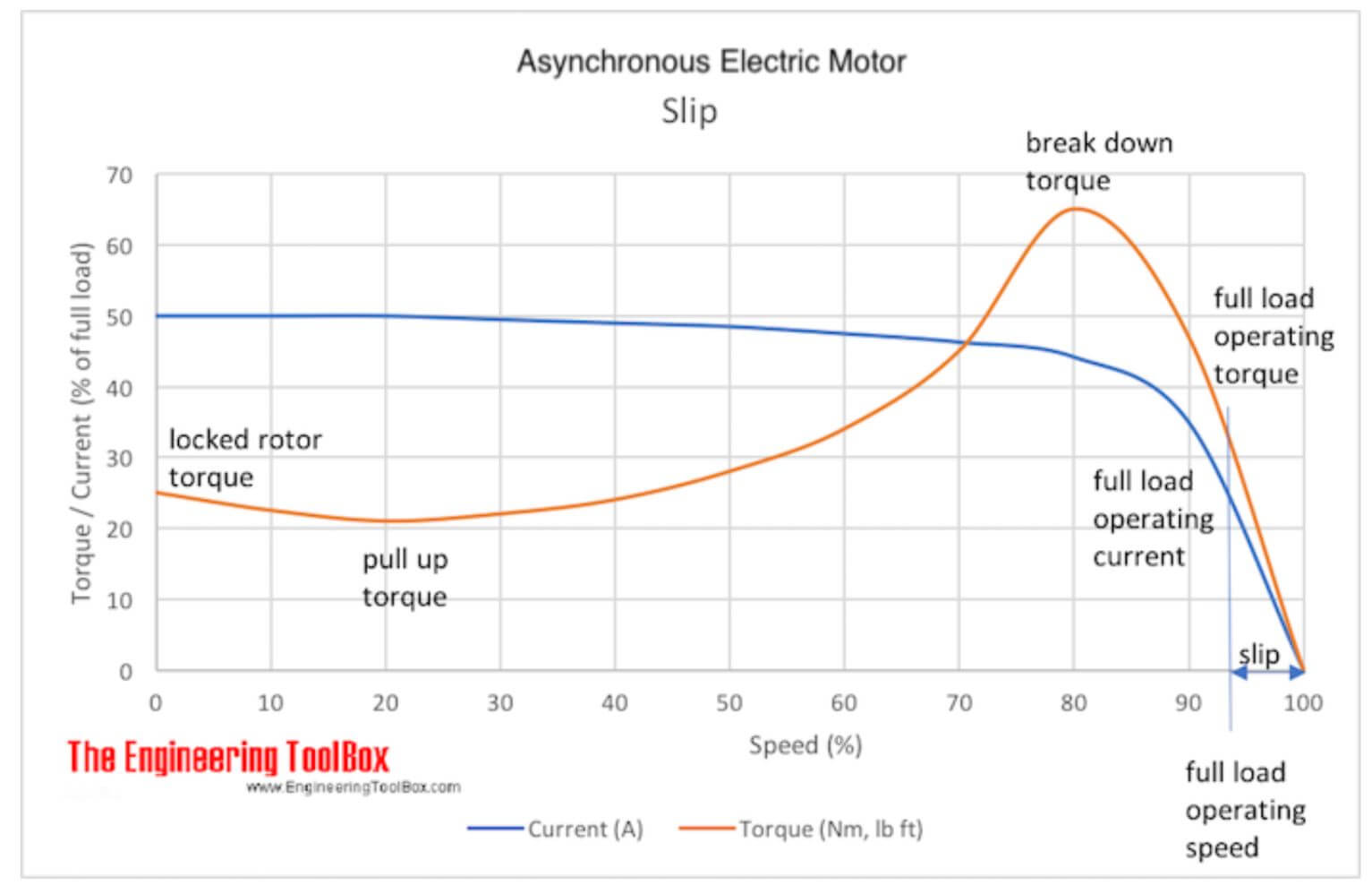
Locked rotor torque
The amount of torque the motor produces when it is energized at full voltage and with the shaft locked
in place is called locked rotor torque. This value is also frequently named “Starting Torque”. It is the
amount of torque available when power is applied to break the load away and start accelerating it up to
speed.
Pull up torque
The lowest point on the torque-speed curve for a motor that is accelerating a load up to full speed is called
Pull up torque.
Breakdown torque
This is the maximum amount of torque that is available from the motor shaft when the motor is operating at full voltage and is running at full speed. The load is then increased until the maximum point is reached.
Full load torque
Full load torque is the rated continuous torque that the motor can support without overheating.
The maximum load torque is reached just below nominal speed.
Constant torque: defines a load where the amount of torque needed to drive the machine remains constant whatever the speed at which it is driven. Types of constant torque loads include:
- conveyors
- cranes
- compressors
- crushers
- mixers
Variable torque: requires low torque at low speeds, and increasing torque as speed increases. Variable torque loads make up a large percentage of motor applications. Types of variable torque loads include:
- Fans
- Blowers
- AHU (Air Handling Unit)
- Chillers
- Most water pumps (irrigation, downhole, submersibles …)
- Centrifugal pumps (often used in sewage treatment)
Fans and blowers are primarily moving air. Centrifugal pumps, however, can move different types of fluids such as oil, coolants, water, etc.
Glossary
Amazing vocabulary from the world of the SmartD drives.
| What | Categories/Tags | |
|---|---|---|
| Acceleration time | Motor Time | Time to reach the motor nominal speed (frequency), starting from Speed 0. |
| AFD | Drive | Adjustable Frequency Drive. One of many names of the device |
| AFE | Drive | Active Front-End. An Active Front-End drive is having two inverter sections: an active rectifier and an inverter/controller. 2 key benefits: - reduce harmonics - can return energy back to the source without adding additional equipment such as braking resistor. |
| AHU | HVAC | Air Handling Unit |
| ASD | Drive | Adjustable Speed Drive. One of many names of the device |
| AWG | Drive Motor | American Wire Gauge. AWG was standardized in 1857 and is used mainly in the United States for the diameters of round, solid, nonferrous electrical wire. |
| BACnet | HVAC Network | An open, standard protocol that allows building automation systems, or subsystems, from different manufacturers to share information and control functions. This protocol is defined by ANSI/ASHRAE Standard 135 and is governed by an ASHRAE committee (www.bacnet.org). |
| BLE | Drive Communication | Bluetooth Low Energy. Wireless network technology. Compared to Classic Bluetooth, Bluetooth Low Energy is intended to provide considerably reduced power consumption |
| Blower | HVAC | Similar to a fan used to push air. |
| Boiler | HVAC | Device for heating water or generating steam above atmospheric pressure. |
| BTU | HVAC | British Thermal Unit, a BTU is the amount of heat required to raise the temperature of one pound of water one degree Fahrenheit. 1 BTU equals 1,055 joules, in heating and cooling terms, 1 "ton" equals 12,000 BTU. |
| Coasting | Drive Motor | Stop energizing the motor and let the motor stopping by itself. |
| Centrifugal Compressor | HVAC | A compressor employing centrifugal force for compression. |
| CO contact | Relay Product | Change over contact. Also named as SPDT-NO (Simple pole double throw). For a relay, the contact names and its schematic refers to de-energized coil. |
| Compressor Reciprocating | HVAC | Compressor which uses a piston cylinder mechanism to provide pumping action. |
| Deceleration time | Motor Drive | Time to reach speed 0 when decelerating from motor nominal speed (frequency). |
| dv/dt filter | dv/dt filtering suppresses inverter output voltage spikes and rapid voltage changes that stress motor insulation. Additionally, dv/dt filtering reduces capacitive leakage currents and high-frequency emissions from the motor cable as well as high-frequency losses and bearing currents in the motor. | |
| E / E / EP | Drive | Acronym for electrical and/or electronic and/or programmable electronic. Safety-related systems that are used to perform safety functions. |
| EMC | Motor Drive | EMC stands for electromagnetic compatibility. It is the ability of electrical/electronic equipment to operate without problems in an electromagnetic environment. Likewise, the equipment must not disturb or interfere with any other product or system in its locality. This is a legal requirement for all equipment taken into service within the EU. |
| EUT | Motor Drive | Equipment under test. Acronym frequently used to name the product/equipment that is tested. |
| Factory setting | Product | Settings when the product is shipped from the manufacturing. |
| Fault | Product Alarm | Fault is an operating state. If the monitoring functions detect an error, a transition to this operating state is triggered, depending on the error class. A "Fault reset" or “Alarm reset” is required to exit this operating state after the cause of the detected error has been removed. Further information can be found in the pertinent standards such as IEC 61800-7. |
| Fault reset | Product Alarm | A function used to restore the drive to an operational state after a detected error is cleared by removing the cause of the error so that the error is no longer active. |
| FLA / FLC | Motor | Full Load Amps / Full Load Current. The amount of current the motor can be expected to draw under full load (torque) conditions. It is written on the nameplate of the motor. |
| Harmonics | Drive | Harmonic currents are created by non-linear loads connected to the power distribution system. Harmonic distortion is a pollution in the electric plant that can cause problems if the voltage distribution caused by harmonic currents increases above certain limits. |
| HVAC/R | HVAC | Heating, Ventilation, Air Conditioning, and Refrigeration. |
| IP code | Motor Drive | Degrees of protection provided by enclosures. |
| IPM | Motor | IPM = interior permanent magnet. IPM motors are synchronous motors that have strong permanent magnets embedded in their rotors. |
| Jog | Motor Drive | A function used to run the motor for a short period of time. Like moving a conveyor. A "jog" command is essentially an energy "pulse". A very quick ramp up and down of voltage and/or current is commanded with the idea that it will generate enough torque to overcome static friction and move the rotor some arbitrary fraction of a revolution. |
| Jump Frequency | Motor Drive | Output frequency within a specified frequency zone to avoid a resonance frequency of a machine. |
| Locked rotor Amps | Motor | The amount of current the motor can be expected to draw under starting conditions when full voltage is applied. Also named starting inrush. |
| MTTFd | Motor Drive Safety | Mean time to dangerous failure or, Expectation of the mean time to dangerous failure. |
| NC Contact | Relay Product | Normally Closed contact. Also named “break contact”. or SPST-NC (Simple pole simple throw) For a relay, the contact names and its schematic refers to de-energized coil. |
| NO Contact | Relay product | Normally Opened contact. Also named “Make contact”. or SPST-NO (Simple pole simple throw) For a relay, the contact names and its schematic refers to de-energized coil. |
| Output Voltage | Drive | The voltage between the output terminals of the VFD. |
| Overhauling | Drive Motor | When the load is moving faster than the designated motor speed. |
| PE | Drive Motor | Protective earthing. Earthing of a point in a system, or equipment, for protection against electric shock in case of a fault. |
| PFD | Drive Safety | Probability of dangerous failure on demand (IEC61508). |
| PFH | Drive Safety | Average frequency of a dangerous failure (EN/IEC61800-5-2). |
| PMSM | Motor | Permanent Magnet Synchronous Motor |
| Power Unit | Drive Motor | Relationship between power units. P (kW) = 0.7457 . P (HP) P (HP) = 1.341 P (kW) |
| PSCC or ISCC | Drive | Prospective short-circuit current. Current which flows when the supply conductor Ps to the circuit are short-circuited by a conductor of negligible impedance located as near as possible to the supply terminals. |
| PTC | Motor Protection | Positive Temperature Coefficient. PTC thermistor probes integrated into the motor to measure its temperature. |
| Rated Torque | Motor | Rated torque in N.m=9550 x (rated motor output in kW / rated motor speed in RPM). Note: the rated motor torque is not a torque generated from the motor. It is a load torque which is permissible in the continuous operation at the rated motor speed. Rated motor speed depends on frequency and number of poles of the motor. |
| Reversing | Motor | Reversing the rotation direction with a drive is easy. The drive can deliver reversing function that DOL starters can’t: a deceleration ramp followed by an acceleration ramp in linear or s-curve shape. |
| Sags | Power Line | Sag is a short voltage decrease down to 90–10% of the root mean square (RMS) voltage magnitude. The duration is from 1/2 cycle up to about 500ms. (Longer duration than 1 minute is defined as an under voltage). For VFD, immunity to sags and related tests are described in IEC61000-4-34 (greater than 16A) and 61000-4-11 (less than 16A) SEMI F47-0706 (Semiconductor Equipment and Materials institute) is also a reference for voltage Sags immunity. |
| Service factor | Motor | The service factor is a multiplier that indicates the amount of overload a motor can be expected to handle. For example, a motor with a 1.0 service factor cannot be expected to handle more than its nameplate horsepower on a continuous basis. Similarly, a motor with a 1.15 service factor can be expected to safely handle intermittent loads amounting to 15% beyond its nameplate horsepower. |
| SFF | Drive Safety | Safe failure fraction (%) (IEC61508). The ratio of the average rate of safe failures plus dangerous detected failures of the subsystem to the total average failure rate of the subsystem. |
| SIL | Drive Safety | Safety integrity level (1-3) (IEC61508). |
| Sine Filter | Drive Motor | The sine filter provides true sinusoidal voltage waveform at the drive output by suppressing the high-frequency voltage components of the drive output. Suppression of the high-frequency voltage components is needed when extra-long motor cables are used. |
| Skilled Person | Drive Motor Safety | Individual with relevant technical education, training and/or experience enabling him or her to perceive risks and to avoid hazards occurring during use of a product. |
| Slip | Motor | In an AC induction motor, the rotor always runs a little slower than the rotating magnetic field in order to generate torque. This difference in speed is named Slip. |
| Stalled | Motor | The status in which the rotor at the motor stator cannot follow the rotating magnetic field because the load applied to the motor is too large or the acceleration or deceleration is too rapid. The motor loses speed. |
| STO | Motor Protection | Safe Torque Off: No power that could cause torque or force is supplied to the motor. |
| Torque Boost | Motor Start Torque | Drive’s function to start a high inertia load. This function allows the motor to apply a high torque at the beginning of the acceleration. The usual and most simple method is to increase the voltage at low frequency to produce adequate torque => increase the V/F for low frequency. Either automatically or manually preset. This is also named torque compensation. |
| V/F control | Motor Control | V/F is a method of controlling a motor in which the voltage and frequency are in a proportional relationship. Therefore a specific current is supplied to the motor to output a specific torque. |
| VFD | Drive | Variable Frequency Drive. One of many names of the device. |
| VSD | Drive | Variable Speed Drive. One of many names of the device. |
This post is also available in: Français