Product Details
- Home
- Clean Power VFDs
- SDB-2-2375-A
SDB-2-2375-A
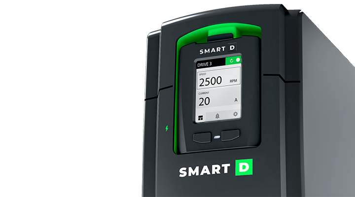
Clean Power Variable Frequency Drive, input 3x 600V, rated output 55A, IP20, embedded AFE
Main features
- Variable frequency drive for AC motors
- Pure sine wave 3-phase power output
- Clean Voltage sine wave, V/f open and close loop
- Field Oriented Control open and close loop
- Multifunctional, digital and analog IOs
- Built-in safe torque off (STO) inputs
- SIL 3 capacity level to IEC61800-5-2
- 24 VDC power supply input
- Dual Ethernet port
- Fire emergency mode
- Configurable Linear and S-curve ramps
- Starting torque boost
- Integrated EMC filters
- Set, monitor, control it with an app
- Pluggable display
- Natural language user interface
Description
The SmartD Clean Power Variable Frequency Drive is a compact AC drive utilizing SmartD’s patented own algorithms combined with WBG transistor technology. Producing a clean and pure sine wave to power and control 3-phase AC induction motors has never been easier. The SmartD VFD has essential features built-in for space, wiring and time savings, it eliminates the need for filters on the output, and guarantees longer motor lifetime.
This post is also available in: Français
SDB-2-2375-A specs
General
| Product function | Variable frequency drive for AC motors |
| Controlled motors | Asynchronous 3-phases motors Synchronous 3-phases motors (Permanent magnet) |
| Control Methods | Clean Voltage sine wave, V/f open and close loop. indirect Field Oriented Control (iFOC) open and close loop |
Power input
| Input Power Voltage | 3 x 600 VAC -15% / +10% | ||
| Input Power Frequency | 50 and 60Hz +/- 5% | ||
| Input line current | rms at 50 °C (122 °F) | Rated input current | 60A |
| Apparent power | 36kVA @600V | ||
| Prospective Line Isc | 100 kA | ||
| THDi | <5 % from 80…100 % of load conforming to IEC 61000-3-12 |
Power output
| Output Current | rms at 50 °C (122 °F) | Normal operation (continuously available without overload) | 55A |
| Heavy duty operation | 40A | ||
| Motor Power kW normal duty (1) | 3x400VAC 50/60Hz | – | |
| Motor Power kW heavy duty (1) | – | ||
| Motor Power HP normal duty (1) | – | ||
| Motor Power HP heavy duty (1) | – | ||
| Motor Power kW normal duty (1) | 3x460VAC 50/60Hz | – | |
| Motor Power kW heavy duty (1) | – | ||
| Motor Power HP normal duty (1) | – | ||
| Motor Power HP heavy duty (1) | – | ||
| Motor Power kW normal duty (1) | 3x560VAC 50/60Hz | max 37.5 KW | |
| Motor Power kW heavy duty (1) | max 30 kW | ||
| Motor Power HP normal duty (1) | 50 HP | ||
| Motor Power HP heavy duty (1) | 40 HP | ||
| (1) motor power values are indicative. They vary with the motor type, technology and manufacturer. The variable frequency drive must not be selected from motor power rating The variable frequency drive must be selected by skilled and experienced personnal. The variable frequency drive must be selecting according to motor FLA, the load’s driving force and the movement cycle, and the operating environment. |
|||
| Maximum Transient Output current | Normal operation | 110% of Normal Duty rated current during 60s every 10 min at 50 °C (122 °F) | |
| Heavy duty operation | 150% of Heavy Duty rated current during 60s every 10 min at 50 °C (122 °F) | ||
| Permissible temporary current boost (motor starting) |
Normal operation | ≥ 110 A at 50 °C (122 °F) during 2s | |
| Heavy duty operation | ≥ 110 A at 50 °C (122 °F) during 2s | ||
| Short-circuit current for immediat tripping | ≥ 170 A at 50 °C (122 °F) | ||
| Output Frequency range of the drive | 0.001 to 0.5 kHz | ||
| Speed drive output Frequency | 0.1 to 120 Hz | ||
| Nominal switching frequency | 105 kHz | ||
| effective switching frequency | 210 kHz | ||
| efficiency | 8 points graph as per IEC61800-9 | ≥ 97% | |
| IE Class | 2 | ||
| Deratings | Ambient temperarure derating | -15…50 °C without derating >50…60 °C , Derate 2% for every 1 °C (1.8 °F) |
|
| Altitude derating | no derating up to 2000 m | ||
Braking
| Braking | Regenerative braking through AFE |
Auxiliary power input
| Voltage | 24 VDC |
| Limits | 20.4 VDC to 28.8 VDC |
| Built in protection of auxiliary power input | Reverse polarity and overvoltage |
Digital I/O's
| Standard to comply with | IEC 61131-2 type 1 | ||
| Digital input numbers | 6 | ||
| Digital inputs common terminal | 1 | ||
| inputs 1 and 2 | Settable by user | usable for encoder | |
| inputs 3 to 6 | Settable by user | settable by user | |
| input logic | wire-able as sink or source, configurable by software default: source |
||
| Source mode logic thresholds | ON: 18 .. 24V / OFF: 0 .. 6V | ||
| Sink mode logic thresholds | ON: 0 .. 6 V / OFF: 18 .. 24 V | ||
| Current consumption | 6mA | ||
| Auxiliary Output power for digital inputs | +24VDC (20% .. +20%) / 100 mA | ||
| Built in protection of Auxiliary output power | overcurrent and overvoltage | ||
| STO (safe torque off) inputs | Number of STO inputs | 2 | |
| SIL capacity | SIL 3 capacity level – conformed to IEC61800-5-2 | ||
| stop category | category 0 | ||
| STO input reaction time | < 20 ms | ||
| STO input filtering time | 3 ms | ||
| Nominal voltage of STO enabling input | 24V | ||
| Maximum input voltage | 28.8V | ||
| Logic threshold | 10V (+/- 5V) | ||
| Low state maximum voltage for disable to SIL3 and Ple |
5V | ||
| Digital output numbers | 3 | ||
| relay 1 | relay output SPDT (form C) | NO Contact | Resistive load, AC: 5 A @ 250 V / DC 5 A @ 30 V |
| NC Contact | Resistive load, AC: 3 A @ 250 V / DC 3 A @ 30 V | ||
| relay 2 and 3 | relays output NO (form A) | Resistive load, AC: 3 A @ 250 V / DC 3 A @ 30 V |
Analog I/O's
| Analog input numbers | 3 | |
| Analog input types | settable by users | 0..10VDC 0..20mA / 4..20mA 0..24VDC Impedance to read PTC temperature sensor |
| Input impedance | 0..10VDC: input impedance > 3.5 k Ohms 0..20mA / 4..20mA: input impedance 165 Ohms 0..24VDC: input impedance > 3.5 k Ohms |
|
| Resolution | 12 bits | |
| Sampling time | 2ms | |
| Accuracy | ± 1% at 25 °C (77 °F) / ± 2% for a temperature variation of 60 °C (108 °F) | |
| Reference power supply for potentiometer | +10 VDC / tolerance ± 2% for the temperature range of 20 °C to 30 °C / Current : maximum 10 mA, short circuit protected | |
| Analog ouput numbers | 2 | |
| Analog output types | settable by users | 0..10VDC ( ≥ 15 mA) 0..20mA / 4..20mA |
| Analog output impedeances | 0..10VDC: output impedance 500 Ohms minimum 0..20mA / 4..20mA: output impedance 500 Ohms maximum |
|
| Resolution | 12 bits | |
| Sampling time | 2ms | |
| Accuracy | ± 1% at 25 °C (77 °F) / ± 2% for a temperature variation of 60 °C (108 °F) | |
| Analog outputs built-in protection | overvoltage and overcurrent |
Communication
| Embedded ports on 2 RJ45 | Modbus TCP |
| Wireless for Settings | BLE |
Dimensions
| Width | 12 in (30.48 cm) |
| Height | 28 in (71.12 cm) |
| Depth | 10 in (25.4 cm) |
| Net weight |
Environment
| Relative humidity | 5…95 % without condensation conforming to IEC 60068-2-3 |
| Ambient air temperature for operation | -15…50 °C without derating 50…60 °C with derating factor 2% for every 1 °C (1.8 °F)” |
| Ambient air temperature for storage | -40…70 °C |
| Cooling | Integrated, replaceable fans |
| Operating altitude | <=2000 m without derating |
| Environmental characteristic | Chemical pollution resistance class 3C3 conforming to EN/IEC 60721-3-3 Dust pollution resistance class 3S3 conforming to EN/IEC 60721-3-3 |
| Ingress Protection IP | IP20 |
| Protection Degree | UL (nema) type 1 |
Applicable standards
| Functionnal safety | UL/IEC 61800-5-1 :2007+AMD:2016CSV |
| EMC | IEC 61800-3 : 2017 emissions ; IEC 61000-4 immunity; IEC 61000-4-11 -34 voltage variations |
| Harmonics | IEC 61000-3-12 ; IEEE 519 |
| Generique | IEC 61800-2 : 2021 |
| EcoDesign / Energy efficiency | IEC 61800-9 |
| Safety standard ( STO) | IEC 61508 part 1 and part2 ; IEC 62061 :2021 |
| Cybersecurity | IEC 62443 |
| Environmental | IEC 60068-2 ; WEEE directive ; RoHS |
| CERTIFICATIONS | UL: pending |
| Product function | Variable frequency drive for AC motors |
| Controlled motors | Asynchronous 3-phases motors Synchronous 3-phases motors (Permanent magnet) |
| Control Methods | Clean Voltage sine wave, V/f open and close loop. indirect Field Oriented Control (iFOC) open and close loop |
| Input Power Voltage | 3 x 600 VAC -15% / +10% | ||
| Input Power Frequency | 50 and 60Hz +/- 5% | ||
| Input line current | rms at 50 °C (122 °F) | Rated input current | 60A |
| Apparent power | 36kVA @600V | ||
| Prospective Line Isc | 100 kA | ||
| THDi | <5 % from 80…100 % of load conforming to IEC 61000-3-12 |
| Output Current | rms at 50 °C (122 °F) | Normal operation (continuously available without overload) | 55A |
| Heavy duty operation | 40A | ||
| Motor Power kW normal duty (1) | 3x400VAC 50/60Hz | – | |
| Motor Power kW heavy duty (1) | – | ||
| Motor Power HP normal duty (1) | – | ||
| Motor Power HP heavy duty (1) | – | ||
| Motor Power kW normal duty (1) | 3x460VAC 50/60Hz | – | |
| Motor Power kW heavy duty (1) | – | ||
| Motor Power HP normal duty (1) | – | ||
| Motor Power HP heavy duty (1) | – | ||
| Motor Power kW normal duty (1) | 3x560VAC 50/60Hz | max 37.5 KW | |
| Motor Power kW heavy duty (1) | max 30 kW | ||
| Motor Power HP normal duty (1) | 50 HP | ||
| Motor Power HP heavy duty (1) | 40 HP | ||
| (1) motor power values are indicative. They vary with the motor type, technology and manufacturer. The variable frequency drive must not be selected from motor power rating The variable frequency drive must be selected by skilled and experienced personnal. The variable frequency drive must be selecting according to motor FLA, the load’s driving force and the movement cycle, and the operating environment. |
|||
| Maximum Transient Output current | Normal operation | 110% of Normal Duty rated current during 60s every 10 min at 50 °C (122 °F) | |
| Heavy duty operation | 150% of Heavy Duty rated current during 60s every 10 min at 50 °C (122 °F) | ||
| Permissible temporary current boost (motor starting) |
Normal operation | ≥ 110 A at 50 °C (122 °F) during 2s | |
| Heavy duty operation | ≥ 110 A at 50 °C (122 °F) during 2s | ||
| Short-circuit current for immediat tripping | ≥ 170 A at 50 °C (122 °F) | ||
| Output Frequency range of the drive | 0.001 to 0.5 kHz | ||
| Speed drive output Frequency | 0.1 to 120 Hz | ||
| Nominal switching frequency | 105 kHz | ||
| effective switching frequency | 210 kHz | ||
| efficiency | 8 points graph as per IEC61800-9 | ≥ 97% | |
| IE Class | 2 | ||
| Deratings | Ambient temperarure derating | -15…50 °C without derating >50…60 °C , Derate 2% for every 1 °C (1.8 °F) |
|
| Altitude derating | no derating up to 2000 m | ||
| Braking | Regenerative braking through AFE |
| Voltage | 24 VDC |
| Limits | 20.4 VDC to 28.8 VDC |
| Built in protection of auxiliary power input | Reverse polarity and overvoltage |
| Standard to comply with | IEC 61131-2 type 1 | ||
| Digital input numbers | 6 | ||
| Digital inputs common terminal | 1 | ||
| inputs 1 and 2 | Settable by user | usable for encoder | |
| inputs 3 to 6 | Settable by user | settable by user | |
| input logic | wire-able as sink or source, configurable by software default: source |
||
| Source mode logic thresholds | ON: 18 .. 24V / OFF: 0 .. 6V | ||
| Sink mode logic thresholds | ON: 0 .. 6 V / OFF: 18 .. 24 V | ||
| Current consumption | 6mA | ||
| Auxiliary Output power for digital inputs | +24VDC (20% .. +20%) / 100 mA | ||
| Built in protection of Auxiliary output power | overcurrent and overvoltage | ||
| STO (safe torque off) inputs | Number of STO inputs | 2 | |
| SIL capacity | SIL 3 capacity level – conformed to IEC61800-5-2 | ||
| stop category | category 0 | ||
| STO input reaction time | < 20 ms | ||
| STO input filtering time | 3 ms | ||
| Nominal voltage of STO enabling input | 24V | ||
| Maximum input voltage | 28.8V | ||
| Logic threshold | 10V (+/- 5V) | ||
| Low state maximum voltage for disable to SIL3 and Ple |
5V | ||
| Digital output numbers | 3 | ||
| relay 1 | relay output SPDT (form C) | NO Contact | Resistive load, AC: 5 A @ 250 V / DC 5 A @ 30 V |
| NC Contact | Resistive load, AC: 3 A @ 250 V / DC 3 A @ 30 V | ||
| relay 2 and 3 | relays output NO (form A) | Resistive load, AC: 3 A @ 250 V / DC 3 A @ 30 V |
| Analog input numbers | 3 | |
| Analog input types | settable by users | 0..10VDC 0..20mA / 4..20mA 0..24VDC Impedance to read PTC temperature sensor |
| Input impedance | 0..10VDC: input impedance > 3.5 k Ohms 0..20mA / 4..20mA: input impedance 165 Ohms 0..24VDC: input impedance > 3.5 k Ohms |
|
| Resolution | 12 bits | |
| Sampling time | 2ms | |
| Accuracy | ± 1% at 25 °C (77 °F) / ± 2% for a temperature variation of 60 °C (108 °F) | |
| Reference power supply for potentiometer | +10 VDC / tolerance ± 2% for the temperature range of 20 °C to 30 °C / Current : maximum 10 mA, short circuit protected | |
| Analog ouput numbers | 2 | |
| Analog output types | settable by users | 0..10VDC ( ≥ 15 mA) 0..20mA / 4..20mA |
| Analog output impedeances | 0..10VDC: output impedance 500 Ohms minimum 0..20mA / 4..20mA: output impedance 500 Ohms maximum |
|
| Resolution | 12 bits | |
| Sampling time | 2ms | |
| Accuracy | ± 1% at 25 °C (77 °F) / ± 2% for a temperature variation of 60 °C (108 °F) | |
| Analog outputs built-in protection | overvoltage and overcurrent |
| Embedded ports on 2 RJ45 | Modbus TCP |
| Wireless for Settings | BLE |
| Width | 12 in (30.48 cm) |
| Height | 28 in (71.12 cm) |
| Depth | 10 in (25.4 cm) |
| Net weight |
| Relative humidity | 5…95 % without condensation conforming to IEC 60068-2-3 |
| Ambient air temperature for operation | -15…50 °C without derating 50…60 °C with derating factor 2% for every 1 °C (1.8 °F)” |
| Ambient air temperature for storage | -40…70 °C |
| Cooling | Integrated, replaceable fans |
| Operating altitude | <=2000 m without derating |
| Environmental characteristic | Chemical pollution resistance class 3C3 conforming to EN/IEC 60721-3-3 Dust pollution resistance class 3S3 conforming to EN/IEC 60721-3-3 |
| Ingress Protection IP | IP20 |
| Protection Degree | UL (nema) type 1 |
| Functionnal safety | UL/IEC 61800-5-1 :2007+AMD:2016CSV |
| EMC | IEC 61800-3 : 2017 emissions ; IEC 61000-4 immunity; IEC 61000-4-11 -34 voltage variations |
| Harmonics | IEC 61000-3-12 ; IEEE 519 |
| Generique | IEC 61800-2 : 2021 |
| EcoDesign / Energy efficiency | IEC 61800-9 |
| Safety standard ( STO) | IEC 61508 part 1 and part2 ; IEC 62061 :2021 |
| Cybersecurity | IEC 62443 |
| Environmental | IEC 60068-2 ; WEEE directive ; RoHS |
| CERTIFICATIONS | UL: pending |
* Specifications are subject to change without notice.
Benefits

Ultra-low harmonics
Clean Power VFD offers ultra-low harmonics, reducing electrical noise and increasing energy efficiency for your equipment.

Filter-less
Clean Power VFD is filter-less, providing cost-effective and maintenance-free operation for your equipment.
Active Front End (AFE)
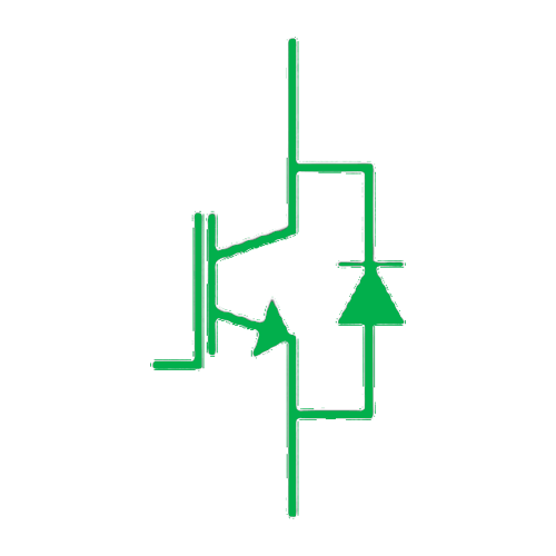
Clean Power VFD features an active front end, enabling power factor near unity, ultra-low harmonics and regenerative braking for improved energy efficiency.
Space divided by 2
Clean Power VFD being of compact design, and eliminating the need for filters, saves up to 50% of space and simplifies equipment wiring.
Clean signal
Clean Power VFD using the last technology of electronic power components, patented algorithm and embedded filters, it produces a clean sine wave.
Extended motor lifetime
Clean Power VFD’s advanced performances reduce motor insulation stress, bearing damage, and electrical noise for a longer motor lifetime.
Our Journey to the Clean Power VFD
Tap the image to see the story
INCEPTION:Simon Leblond and Simon Caron create SmartD Technologies Inc, in 2018, Montreal Quebec.

INNOVATION: SmartD builds the first Wide-bandgap-based VFD technology on the market - offering Clean Power in a way that has not been done before. To achieve this level of technology, SmartD work with some of the most advanced WBG specialists in the industry.
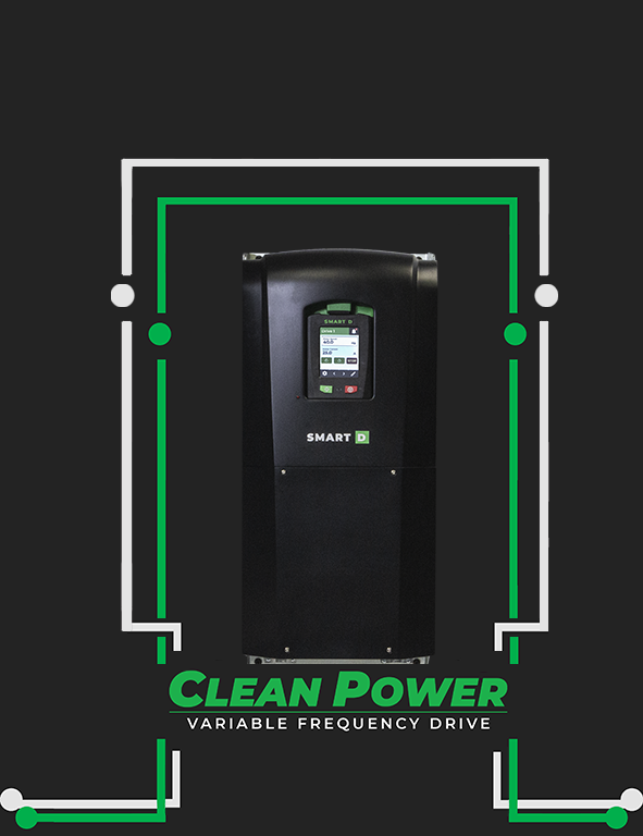
IMPACT: Partnerships are established with SE Ventures, the Power Electronics and Industrial Control Research Group (GRÉPCI), PME MTL, and the Canada Research Chair in Electrical Energy Conversion and Power Electronics.

VFD Selection Made Easy
Simpler from A to Z
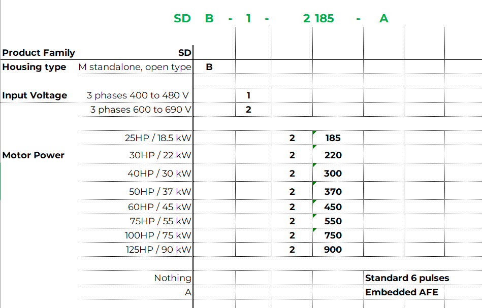
Easiness starts with the selection of the right product. The offer structure of SmartD’s Clean Power VFD is built to ease the decision and avoid complex choices between multilevel of options
Easiness starts with the selection of the right product. The offer structure of SmartD’s Clean Power VFD is built to ease the decision and avoid complex choices between multilevel of options
Book A Demo Right Now!
SmartD Clean Power is real and it is ready to revolutionize motor control. Don’t just take our word for it, see it for yourself.
Frequently Asked Questions
A variable frequency drive (VFD) is an electronic device that controls electric motor speed by varying the frequency and voltage supplied to the motor.
A VFD adjusts the motor’s speed to match the load requirement, this helps to drastically reduce energy consumption.
Other names for a VFD are variable speed drive, adjustable speed drive, adjustable frequency drive, AC drive, and inverter.
SmartD’s Clean Power variable frequency drive generates pure-sine electrical signals in a package half the size that is twice as efficient.
Forget messy cables and bulky filters. Experience Clean Power in a compact footprint.
3 cables in, 3 cables out. That's it. Set it up and let it do its thing in under 30 minutes.
Our products are IoT, BMS and SCADA ready.
Ethernet and Modbus connectivity for integration to Cloud, BMS and SCADA systems.
The SmartD Clean Power VFD will be available for purchase Q3, 2022.
